

MEDICAL LEGAL PANEL - TRAUMA & EXTERNAL FIXATION OF RIGHT KNEE
MScBMC @ UofT

This illustration was created in Stephen Mader's class for the Masters of Biomedical Communications program at the University of Toronto. This was a group project completed by myself, Cynthia Pham, Athena Li, and Vicky Lin. Each of us was tasked with creating a panel for a medical-legal case study, and this illustration was my contribution to the final piece.
TARGET AUDIENCE
Jury composed of General Lay Audience
TOOLS USED
Adobe Photoshop
Adobe Illustrator
RadiAnt DICOM Viewer
1) RESEARCH
The John Doe in this case suffered a fall, resulting in a fracture of their right proximal tibia, with significant comminution of the tibial plateau. We were given Mr. Doe's relevant reports and health records and asked to construct illustrations to support the plaintiff's case after post-operative complications.
We, as a group, spent a significant amount of time going through the patient's hospital information to identify the timeline of events, from the initial injury, to the post-op checkups. This was important to do because the patients story was complicated and understanding the sequence of events would allow us as well as the viewer of the final product to get a better sense of the story as a whole, as well as the suffering the patient enduring during the ordeal. We felt that this timeline was significant enough to implement it into the final illustrations to act as a guide for each part in the panel series.
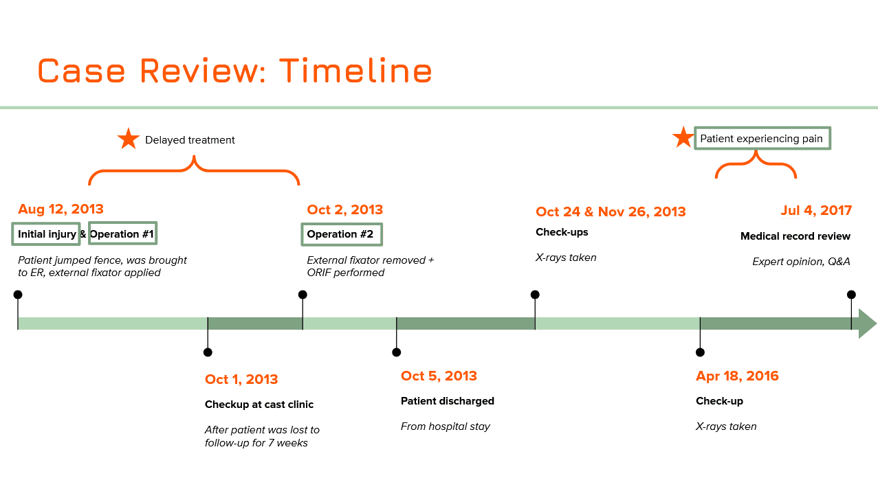
Figure 1:
The timeline of events of John Doe's injury, treatment, and recovery, based on their hospital records.
In addition, I was tasked with determining the extent of the patient's injuries. As part of the case study, we were given John Doe's trauma CT imaging for analysis. I was able to bring this data into RadiAnt DICOM VIEWER to create 3D representations from which we as a group could use as reference.
Figure 2:
Recreation of John Doe's traumatic injury based on their CT imaging results.
Using the information gleaned from this 3D representation, we were able to corroborate the initial diagnosis of a Schatzker Type VI fracture of the right tibia.

Figure 3:
Corroborating John Doe's injury with a Schatzker Type VI fracture.
We also attempted to recreate the mechanism of injury using rudimentary paper maquettes and illustrations to get a better sense of HOW the tibia broke into so many pieces. While this is speculative, we used information given in the medical reports as well as the various changes in skeletal anatomy following the injury to construct a "best-possible" explanation of what forces could have contributed to the fractures. After multiple discussions and recreations with group members, we eventually decided that when Mr. Doe hit the ground with his foot, the knee assumed a valgus position, causing the femur to drive downwards into the tibia. This would have caused the lateral fragment to fracture and be pushed aside by the lateral femoral condyle while the medial fragment would be driven downwards into the tibia. We used this reconstruction to help guide our understanding of the mechanism of injury.

Figure 4:
Determining the details of the mechanism of injury
2) INITIAL SKETCHES
It was at this time that our group decided to split up John Doe's timeline into four major sections, each of which would be assigned for each person in the group to tackle as an individual panel in our final piece. The four sections of the timeline that we agreed on were:
Mechanism of Injury
Trauma and External Fixation of Right Knee
Internal Fixation of Right Knee
Post-Op Complications
I was given the task of creating the second panel in the series: Trauma and External Fixation of the Right Knee. Within this section, I needed to convey the extent of the injury to the patient's knee and tibia as well as the initial treatment that was provided in the Emergency Room (in the form of an external fixation).
For the layout of the illustration, I came up with a few different option. In this first option, I kept things simple and planned to provide areas that illustrated the "Initial Injury", the "External Fixation" following the injury, as well as the delayed "Cast Clinic Checkup" before the actual surgery was conducted.
PROS:
Each section was corroborated with a date on the timeline, making it easier to see understand the sequence of events.
I decided to include an anatomical representation of leg with the external fixation device to help viewers visualize how an external fixation device is installed and maintained. I felt this was necessary because external fixation devices viewed on a 2D representation can be tricky to perceive, so I felt a 3D representation would best convey the idea of the device poking out of John Doe's leg.
CONS:
The view of the 3D representation of the leg is quite small, and may be difficult for viewers in a jury box to properly appreciate. We felt as a group that something so important in contributing to the viewer's understanding of the case should have more real estate on the panel dedicated towards it. We decided to instead move the "Case Clinic Checkup" section to the next panel, and refocus this panel to specifically discuss the trauma Mr. Doe received and the immediate treatment that was done (specifically the external fixation).

Figure 5:
Layout Option 1 - Rough layout covering topics related to initial injury, external fixation, and followup check.
My next layout ideation attempted to address the issues from the first, specifically the size of the 3D representation of the externally fixated leg. I did this by moving the "Cast Clinic Checkup" section to the next panel. In addition, we also tried to move the "Initial Injury" section to the previous panel, so that this panel would specifically discuss External Fixation alone. I included initial trauma views as comparison against the externally fixated knee, but for the most part, the focus was on external fixation.
PROS:
Having this panel specifically focus on External Fixation makes the presentation of information easier to digest for the viewer, as only topic is presented here.
Inclusion of Lateral views would help the viewer understand how external fixation works.
CONS:
Moving sections to other panels would make conveying information on those panels more difficult. Solving one problem here would just create another problem somewhere else. We specifically wanted dedicate space on our first panel to show our hypothetical mechanism of injury, and moving the initial injury to this panel would detract from this.
the 3D representation of the externally fixated leg is still small
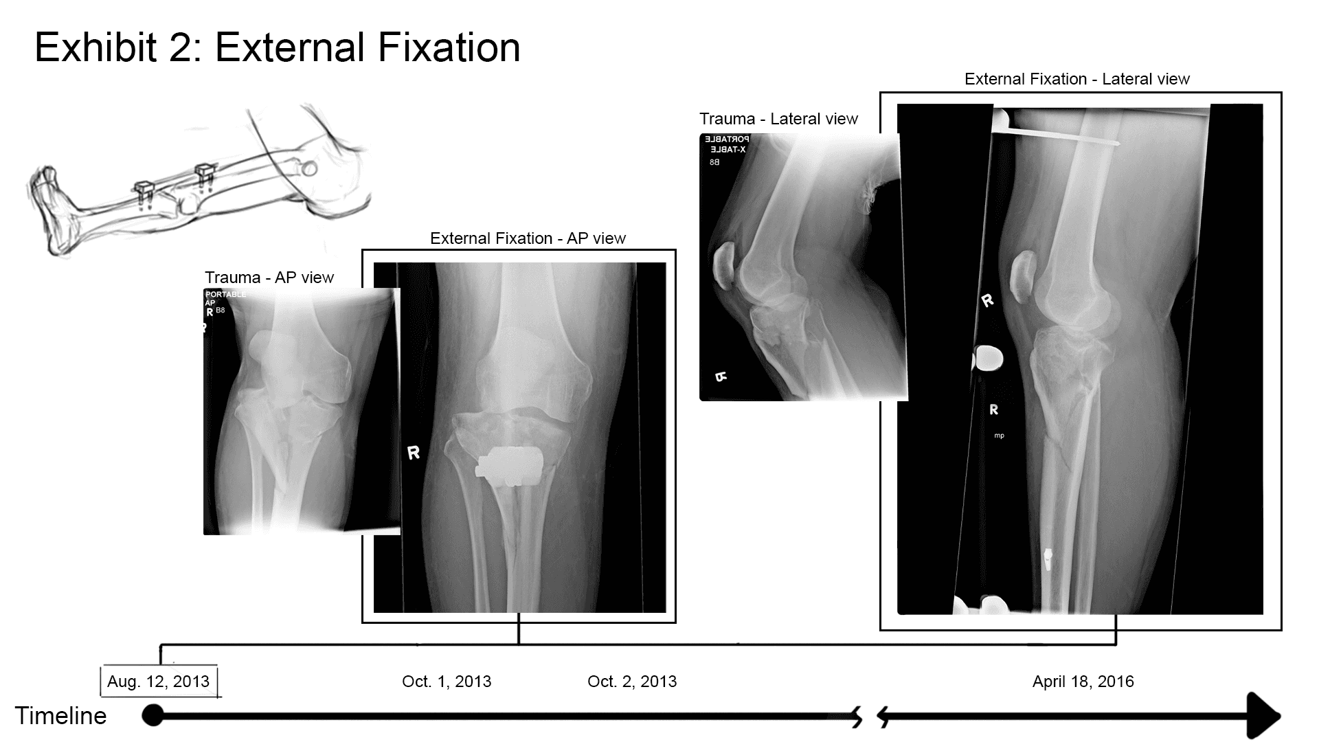
Figure 6:
Layout Option 2 - Rough layout covering topics related mainly to external fixation.
The last layout (that we eventually adopted for the most part) brought back the "Initial Injury" section. This would be presented in comparison with the "External Fixation" view on the opposite side of the page. Both of which would be shown as AP views - we decided to remove the Lateral views, as most of the fracture dislocation was very apparent on the AP view. In the middle of the illustration would be the 3D representation of the externally fixated leg. I felt the flow of this composition worked well, as images from left to right followed the sequential order of events (from initial injury => to external fixation in the OR => the result after external fixation).
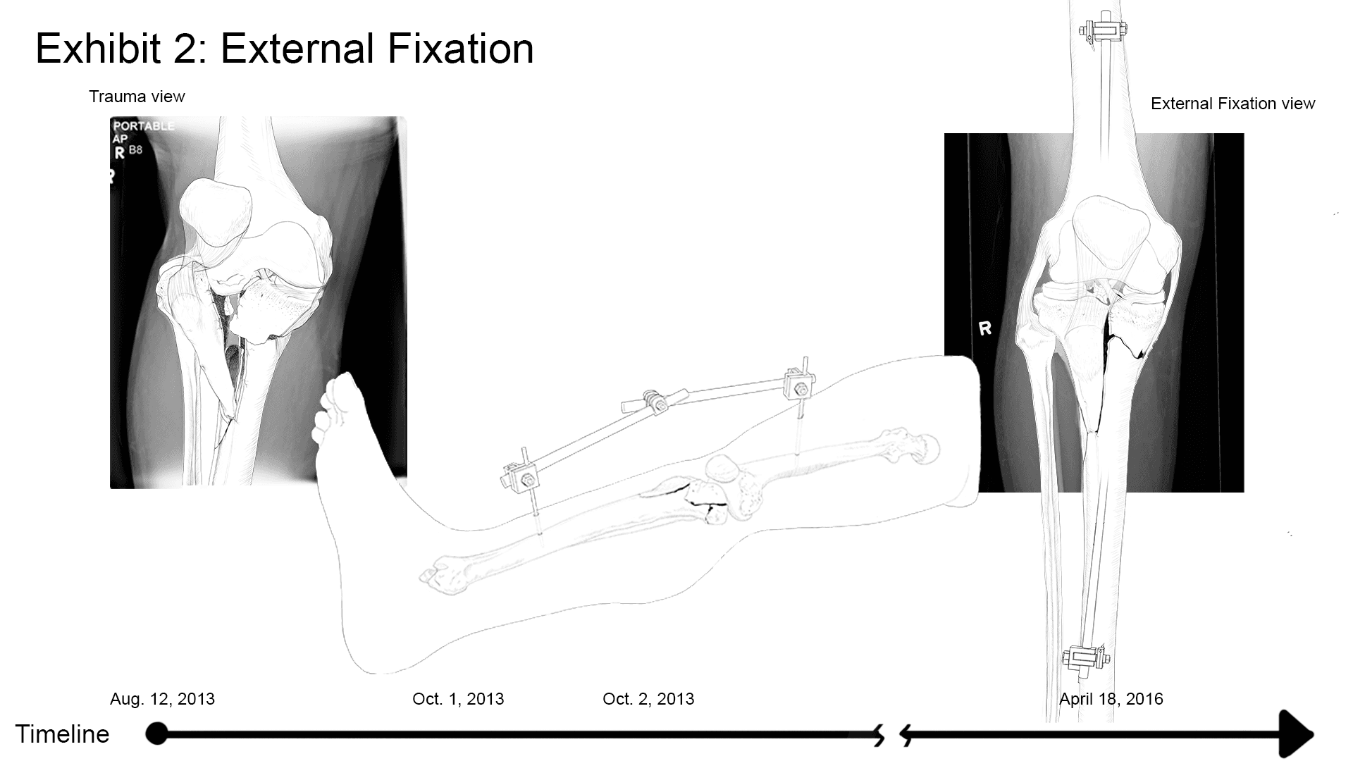
Figure 7:
Layout Option 3 - Rough layout showing comparison between initial injury and external fixation.
Based on the layout chosen, I would need to create three sketches:
AP view of initial injury
3D representation of external fixation
AP view of external fixation
I used multiple sources of data to construct as accurate a depiction of the injury as possible. Sources include the 3D reconstruction from RadiAnt DICOM Viewer, trauma x-rays of John Doe, as well as medical reports that describe in detail the fragmentation of the proximal tibia, and OR notes that described pin placement and specific devices used.


Figure 8:
Initial sketches
03) RENDERING
To maintain consistency between the different panels, a style guide was created that included a colour palette. I used these colours to lay down a flat colour layer, upon which I added further shading and lighting layers.
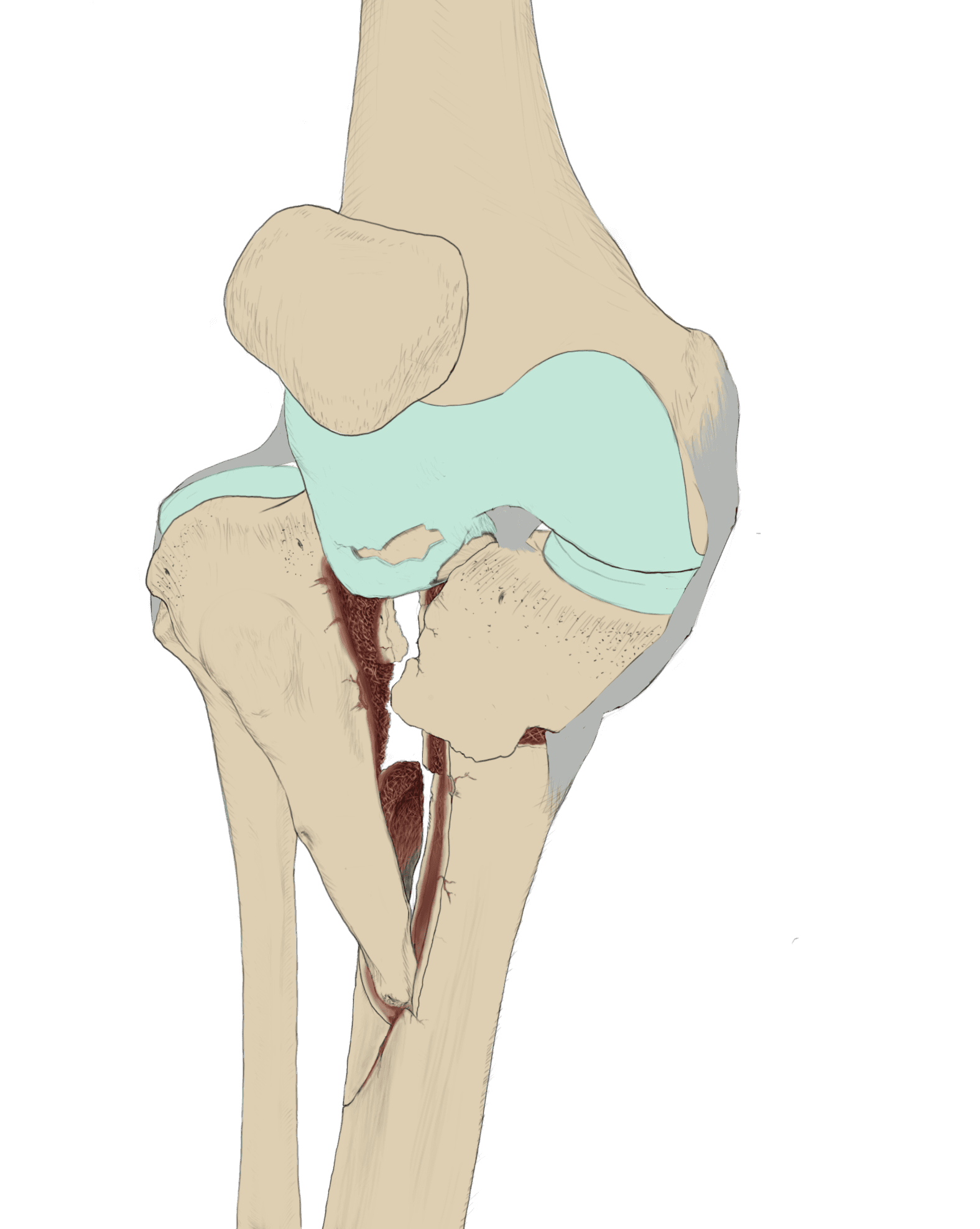
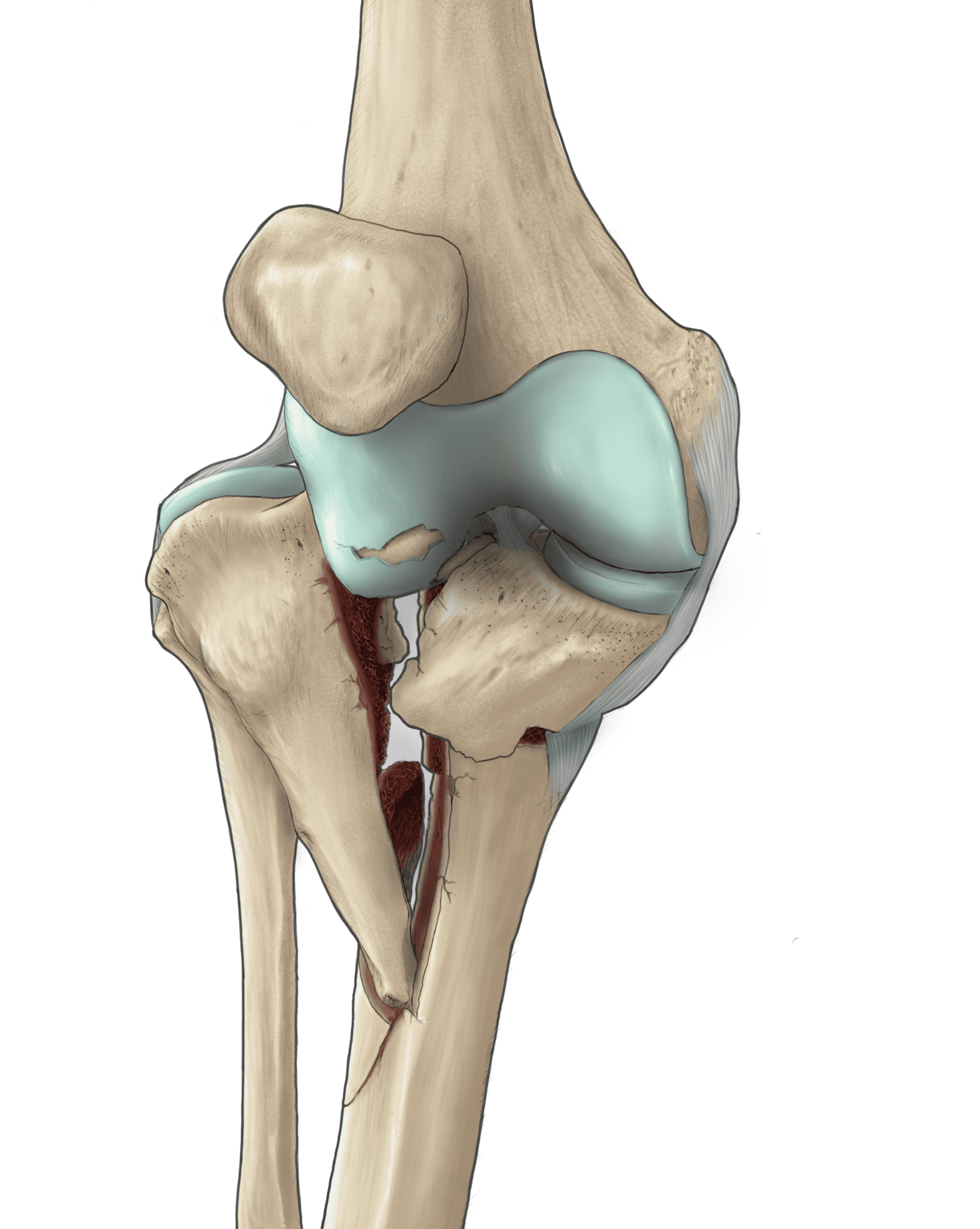
Figure 9:
AP trauma view, showing initial sketch => flat colours => rendered

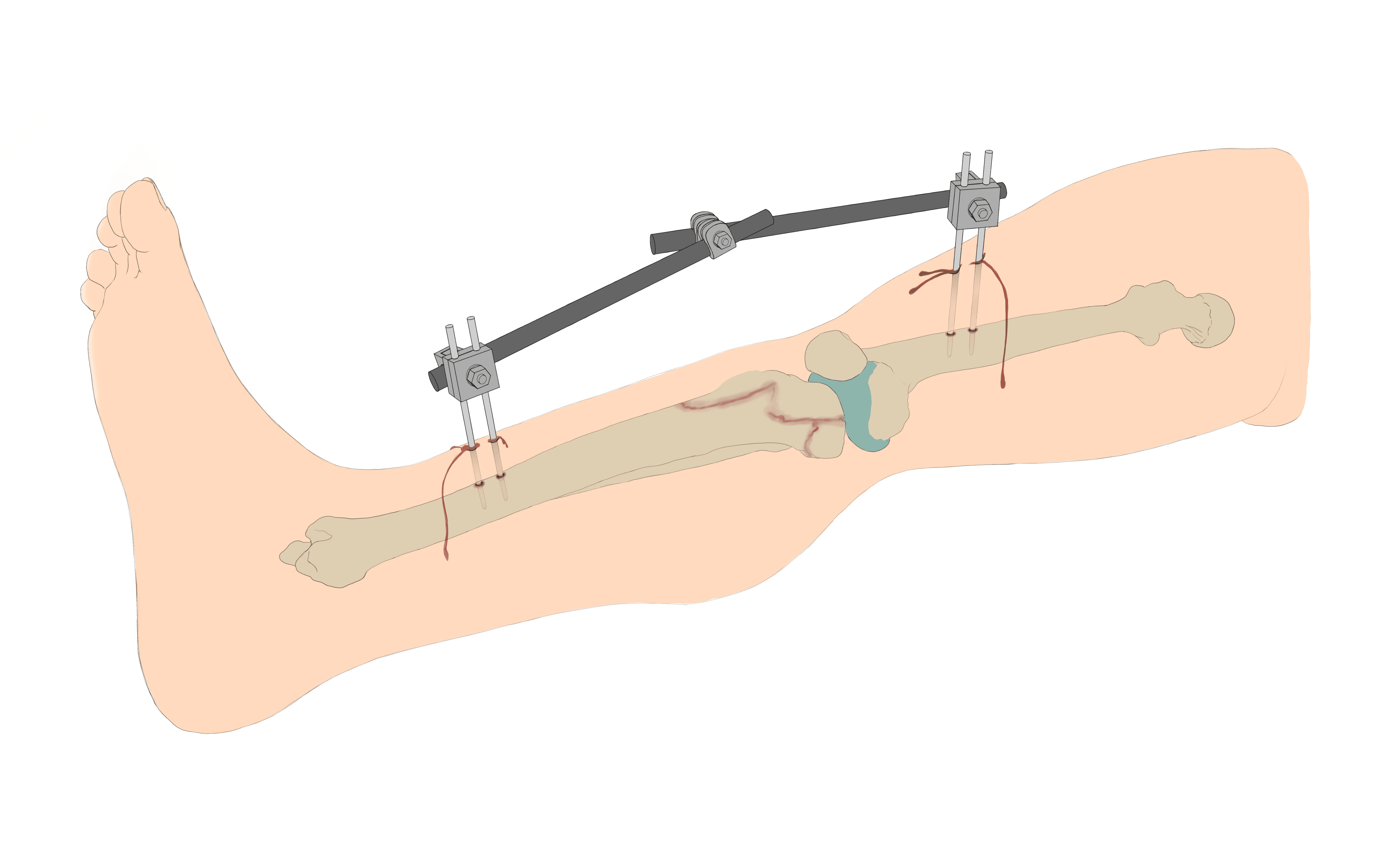

Figure 10:
3D Representation of externally fixated leg, showing initial sketch => flat colours => rendered
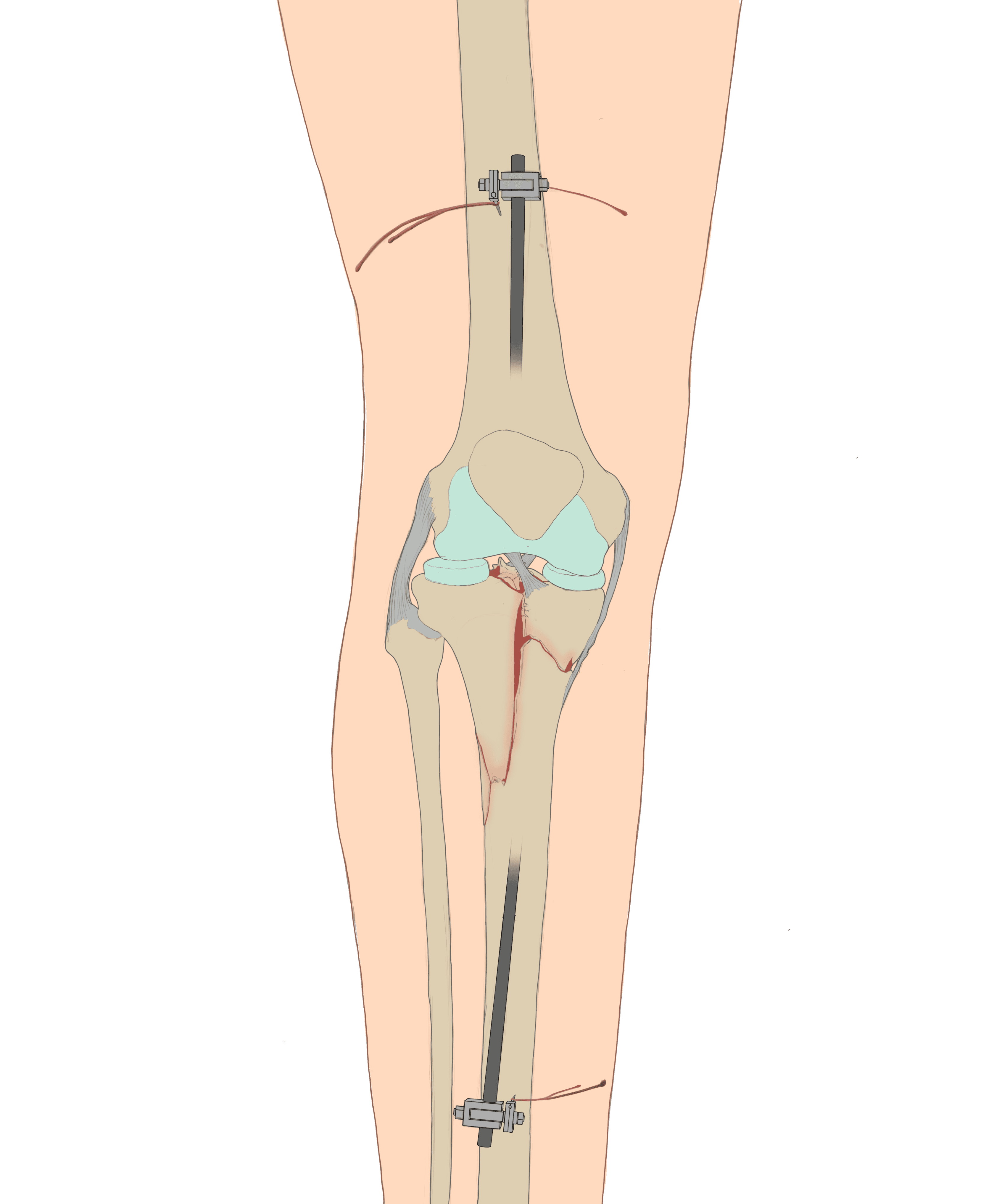
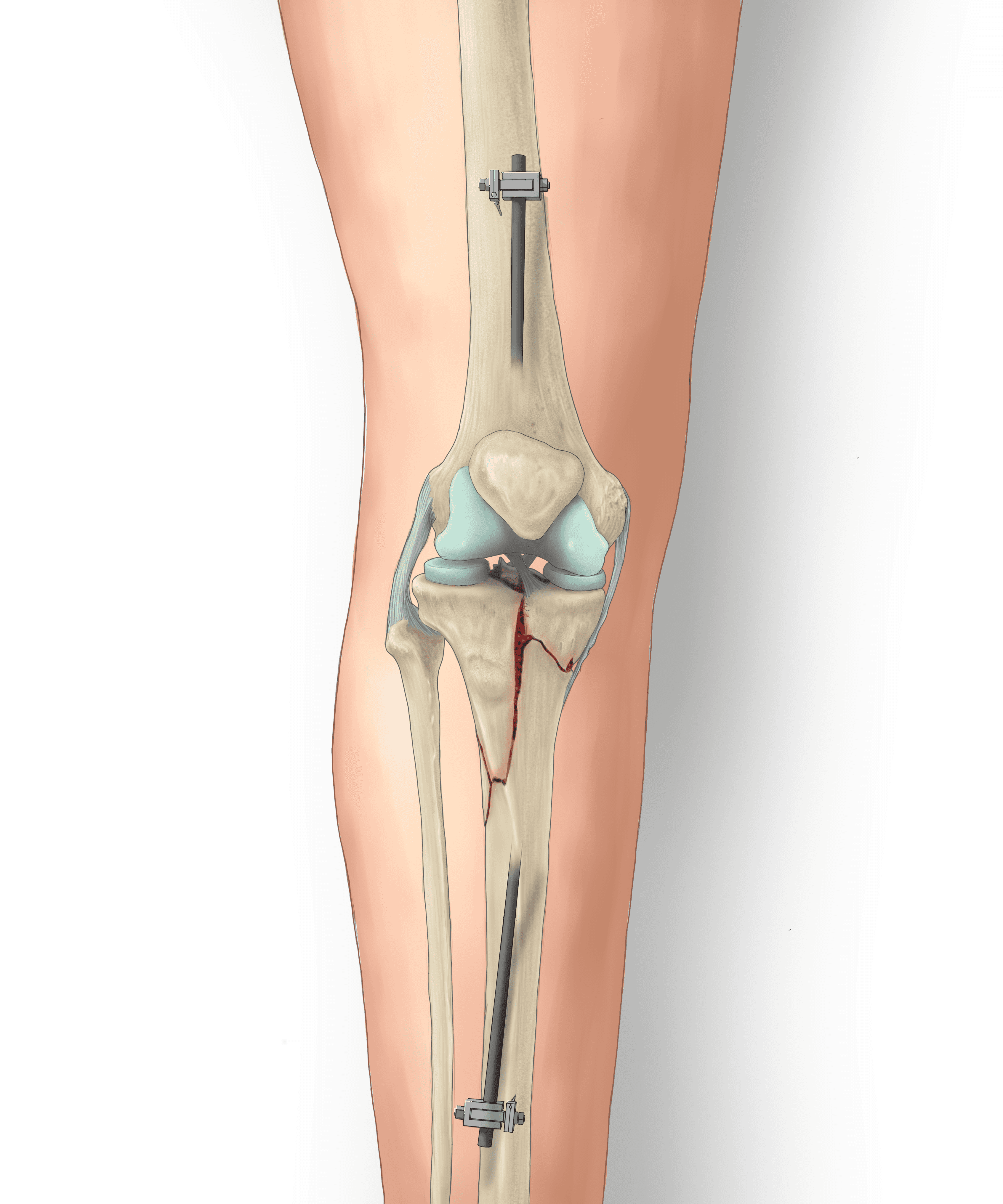
Figure 11:
AP view of External Fixation, showing initial sketch => flat colours => rendered
04) FINAL EXHIBIT
Putting all the pieces together to form the final layout was only half the battle. It was only after combining all of our pieces together that we formed a cohesive exhibit that tied together John Doe's entire story.
Panel 1: "Mechanism of Right Knee Injury" by Vicky Lin
Panel 2: "Trauma & External Fixation of Right Knee" by yours truly, Shanghar Roy Kulananthan
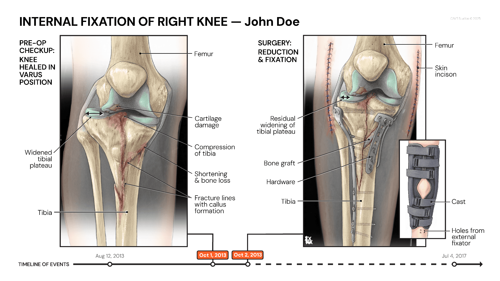
Panel 3: "Internal Fixation of Right Knee" by Athena Li
Panel 4: "Post-Op Complications" by Cynthia Pham


Navigation
Contact